

Car Battery Charger Testing: What to Verify Before Mass Production
Sep 18,2026
A working sample can still fail after mass production. The unit may charge a new battery in the office yet show output error, excess heat, slow charging or false fault messages once thousands of units reach customers. At Parwatt I see these gaps create large return waves for buyers who approved products too quickly.
Car battery charger testing before mass production must cover rated output, complete charging curves, temperature rise, protection behavior and consistency with the approved sample. A simple voltage check is not enough. In 2026 buyers who lock the golden sample, BOM and test limits prevent small design differences from becoming large-scale returns.
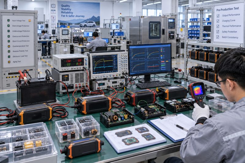
I have worked with automotive accessory wholesalers and importers for years as general manager at Parwatt New Energy. We supply car battery chargers and related products. I regularly review cases where a sample performed acceptably yet production units drifted in voltage accuracy, thermal behavior or stage timing. Our range in the car battery charger category is released only after full performance and consistency checks. In this article I explain what B2B buyers should verify before approving a car battery charger for mass production in 2026.
Why a Working Sample Can Still Fail After Mass Production?
A sample that successfully charges one battery does not prove the design is ready for volume. Output accuracy, component margins, thermal design, charging-algorithm stability and production consistency may still be insufficient. Once the product is made in quantity, these weaknesses appear as slow charging, unexpected fault lights, overheating or early failures.
A working sample can still fail after mass production because single-battery success does not prove voltage accuracy, thermal margin, algorithm stability or batch consistency. These issues surface later as returns and customer complaints.
Hidden Weaknesses That Appear Only at Scale
I have examined production lots that delivered lower current than the sample. A critical power component or transformer had been substituted, or the control calibration had drifted. Customers reported longer charge times and incomplete charges.
Temperature problems often remain hidden in short office tests. When units run at rated current in warmer environments or with restricted ventilation, power devices and capacitors exceed safe limits. Returns then cite overheating or automatic shutdown.
Charging-stage timing can also shift. Absorption periods that were adequate on the sample become too short or too long on production firmware or with slightly different sensing components. Batteries leave the charger undercharged or are held at elevated voltage longer than intended.
False fault detection increases support load. Production units may interpret normal battery behavior as an error because thresholds were tuned only on the original sample.
Here is a table that links sample-level gaps to field problems:
| Sample Limitation | What Remains Unproven | Typical Field Result | Business Impact |
|---|---|---|---|
| Single new battery only | Behavior on aged or low-SOC batteries | Incomplete charge or false faults | Returns and poor reviews |
| Short test duration | Thermal equilibrium | Overheating after longer use | Safety complaints |
| No input-voltage sweep | Performance at line limits | Inconsistent charging | Support tickets |
| Unlocked BOM / firmware | Component or software drift | Batch-to-batch variation | Large return waves |
| No protection injection | Real fault response | Missing or late protection | Reputation and claim risk |
This table reflects the patterns I see when production problems are traced backward. At Parwatt we require broader evidence before any charger in our car battery charger category moves to volume.
In 2026 the cost of a late discovery is higher because online reviews spread quickly and platforms enforce stricter quality expectations. Thorough pre-production testing is a commercial necessity.
The Testing Mistakes That Give Buyers False Confidence
Several common testing shortcuts create false confidence. Buyers measure only open-circuit voltage, test with a single healthy battery, run the charger for a few minutes, or simply accept the supplier’s report. These practices miss regulation under load, behavior across battery states, thermal limits and protection performance.
Testing mistakes that give false confidence include relying on open-circuit voltage, using only one new battery, testing for too short a time, and accepting supplier reports without independent verification under varied input, load and temperature conditions.
Shortcuts That Hide Real Risks
Open-circuit voltage confirms that the charger powers on and that the display or indicator works. It does not prove the unit can deliver rated current or hold the correct voltage while charging.
A single new, fully charged battery is an easy load. It does not reveal how the charger behaves with a deeply discharged battery, an aged battery, or a different chemistry. Many smart chargers also wait for a valid battery signature before starting; a quick voltage check may never exercise the full algorithm.
Short test times miss thermal rise. Components and enclosures may stay within limits for ten minutes yet exceed them after thirty or sixty minutes at rated output.
Supplier test reports are useful starting points but are not a substitute for independent checks. Reports may use different equipment, different batteries, or idealized conditions that do not match the buyer’s target market.
Input voltage, ambient temperature and consecutive-cycle testing are often omitted. Real mains voltage varies; warehouses and vehicles experience heat; users may charge more than one battery in sequence.
Here is a table of common testing mistakes:
| Mistake | What It Misses | Better Practice |
|---|---|---|
| Open-circuit voltage only | Loaded regulation and current | Measure voltage and current under load |
| One new battery | Low-SOC and aged-battery behavior | Test multiple states of charge and types |
| Short run time | Thermal equilibrium | Run to stable temperature at rated load |
| Supplier report only | Independent verification | Repeat critical tests with own or third-party setup |
| No input / temperature sweep | Boundary performance | Test at voltage and ambient limits |
| No consecutive cycles | Duty-cycle and heat accumulation | Run repeated charge cycles |
This table helps buyers strengthen their test plans. At Parwatt we avoid these shortcuts when qualifying products for the car battery charger category.
I advise every buyer to treat the supplier report as one data source and to generate an independent data set before approval. False confidence is more expensive than thorough testing.
A Complete Performance Test for Car Battery Chargers
A complete performance test exercises the charger under realistic and boundary conditions. It includes output voltage and current accuracy, the full charging curve, behavior with different battery capacities and states of charge, efficiency, temperature rise, standby power, mode switching, protection functions and resting voltage after charge.
A complete performance test covers rated output, full charging curves, multiple battery conditions, efficiency, thermal rise, standby consumption, mode behavior, protections and post-charge voltage. Calibrated instruments and both controlled loads and real batteries are required.
Core Test Sequence
Begin with input-power verification at the nominal and limit voltages of the target market. Confirm that the charger starts and operates without stress.
Measure output voltage and current under controlled load at several points up to the rated current. Compare results with the specification for accuracy and regulation.
Record a complete charging curve on a representative battery or battery simulator. Capture voltage, current, time and temperature from connection through every stage until maintenance or termination. Note transition thresholds and total charge time.
Repeat key portions of the curve with batteries at different states of charge and, where relevant, different chemistries or capacities within the claimed range.
Measure efficiency at rated and partial loads if energy performance matters for the market.
Run thermal tests at rated load until temperatures stabilize. Record values at power devices, magnetics, capacitors, PCB hotspots, enclosure, cables and clamps. Include elevated ambient and restricted-ventilation conditions where appropriate.
Check standby or no-load consumption and any sleep behavior.
Verify mode selection and indication for each claimed battery type or program.
Inject controlled faults to confirm reverse-polarity, short-circuit, overcurrent, overtemperature, missing-battery and timeout responses.
After a full charge, measure the resting battery voltage over a defined period to confirm that the maintenance stage behaves as intended.
Here is a structured performance-test outline:
| Test Area | Key Measurements | Purpose |
|---|---|---|
| Input range | Operation at min / nom / max voltage | Boundary reliability |
| Output accuracy | Voltage and current under load | Regulation quality |
| Charging curve | V, I, time, temperature per stage | Algorithm correctness |
| Battery variation | Different SOC and types | Real-world coverage |
| Thermal rise | Component and enclosure temperatures | Safety and durability |
| Efficiency / standby | Power conversion and idle draw | Performance and compliance |
| Protections | Fault injection responses | Safety validation |
| Post-charge rest | Voltage stability in maintenance | Long-term behavior |
This sequence produces a data set that can support a confident production decision. At Parwatt we apply a comparable full-sequence test to every new charger design in our car battery charger category.
I recommend that buyers prepare a written test protocol with equipment list and pass limits before samples arrive. The protocol keeps every evaluation consistent and auditable.
How to Compare the Approved Sample with Production Units
Once a sample is approved it must become the reference. The golden sample, bill of materials, PCB revision, firmware version and critical component list should be locked. Pre-production and bulk units are then tested with the same equipment, load conditions and acceptance criteria so any deviation is visible.
Compare production units with the approved sample by locking the golden sample, BOM, PCB version, firmware and key components. Use identical test equipment and limits at pre-production and bulk stages to detect drift before large quantities are shipped.
Design Control and Comparison Methods
Seal and label the golden sample. Store it under controlled conditions so it remains available for side-by-side checks.
Freeze the approved BOM, including manufacturer and part number for critical power and sensing components. Any proposed change must trigger a re-evaluation of the affected performance and safety items.
Record the exact PCB revision and firmware version that passed the full test. Production units must match these versions unless a formal change process has been completed.
At pre-production or first-article stage, draw units from the actual process and run the same core performance and protection tests used on the golden sample. Compare numerical results against the original data and the specification limits.
During mass production, include statistical sampling of output accuracy, thermal indicators and critical protection functions. Use the same measurement methods so results remain comparable over time.
When a discrepancy appears, quarantine the affected lot, identify the root cause, and decide on rework, sorting or design correction before further shipment.
Maintain a change log that links any component or firmware update to the corresponding re-test evidence.
Here is a comparison and control checklist:
- Golden sample sealed and archived with test data
- BOM locked with critical component identification
- PCB revision and firmware version frozen
- Identical test methods and limits at every stage
- Pre-production units fully compared with golden-sample results
- Outgoing sampling of key performance and protection items
- Clear quarantine and disposition rules for non-conforming lots
- Formal change control with re-validation requirement
- Traceability between production batches and test records
- Periodic re-check of retained golden sample if needed
At Parwatt we enforce this design-control loop for chargers supplied to partners. The same discipline protects consistency across our car battery charger category and related lines such as car air pumps.
Buyers who lock the reference and compare production units against it catch problems while the quantity at risk is still small. That early detection is the main purpose of the comparison process.
Turn Test Results into a Mass-Production Approval Checklist
Test results become useful only when they are converted into a written approval checklist. The document should define test methods, equipment accuracy requirements, numerical limits, sample quantities, required raw data and the rules for handling non-conformances. Mass production should start only after every critical item is closed.
Turn test results into a written mass-production approval checklist that specifies methods, equipment, limits, sample sizes, data records and non-conformance handling. Approve volume production only after all critical items are closed against the checklist.
Content of an Effective Approval Checklist
List every required test with a short method description and the measurement equipment accuracy needed. Vague instructions produce inconsistent results.
State numerical pass and fail limits for voltage, current, temperature, timing and protection response. Include tolerances that reflect both product specification and measurement uncertainty.
Define how many units must be tested at sample, pre-production and bulk stages. Higher-risk items may need larger sample sizes.
Require original data—curves, temperature logs, fault-response records—to be attached to the approval file. Summary statements without data are insufficient.
Describe the disposition process for failures: re-test, root-cause analysis, corrective action and, if necessary, design change and re-validation.
Include sign-off fields for the buyer’s technical reviewer and the supplier’s quality representative. Both parties should acknowledge that the checklist has been completed.
Reference the locked golden sample, BOM and firmware version so the checklist remains tied to a specific design configuration.
Review the checklist after the first production shipments and after any significant field feedback. Update limits or methods when evidence shows they are incomplete.
Here is a concise approval-checklist framework:
- Test methods and required equipment accuracy
- Numerical limits for every critical parameter
- Sample quantities at each approval stage
- Requirement for raw data attachment
- Non-conformance and corrective-action rules
- Link to golden sample, BOM and firmware version
- Dual sign-off by buyer and supplier
- Change-control trigger for any design update
- Post-launch review and checklist update rule
- Archiving location for the complete approval file
At Parwatt we close every charger project with a comparable written checklist before volume release. Partners who adopt the same practice gain objective evidence and a clear audit trail. Further product information is available across our car battery charger category and our main catalog.
A completed checklist does not guarantee zero field issues, yet it dramatically reduces the chance that known weaknesses escape into mass production. That reduction is the practical goal of the entire testing effort.
Conclusion
A car battery charger should not be approved for mass production after a simple voltage check. At Parwatt we require full performance, thermal and protection evidence before any design is released to volume. Buyers need evidence that the unit can deliver its rated output, follow the correct charging profile, control temperature and respond safely to abnormal conditions. Testing should combine calibrated instruments, programmable loads or battery simulators, and real batteries at different states of charge. The approved golden sample, BOM and firmware must then be locked so that production units can be evaluated against the same baseline. A documented test plan makes supplier decisions more objective and prevents small engineering differences from becoming large-scale returns.

--- END ---
Related Posts
Business Ideas

Business Ideas

Business Ideas

Business Ideas


